How Is Math Used in Industrial Design
When Design, Engineering & Mathematics Come Together
Case Study of Designing Star Alliance Seat Map SDK
![]()
A few months back, I was commissioned to work on designing a series of Mobile SDKs for the world's largest airline alliance, Star Alliance. The objective was to create fluid SDKs where any partner airline could plug in their mobile apps and customize them while the overall experience stayed consistent.
One of the more challenging aspects of the project was designing the Seat Map SDK. I thought it would be an interesting case study to share. Unlike some conventional views that design is JUST how it looks/feels, very often design is closely knit with how it works. At least as a product designer most of challenges I work on are a combination of how a product looks, feels, and works.
Note: Admittedly this post gets a bit geeky towards the end, but I thought some of you might enjoy the details.
Problem
If you have ever tried booking and selecting your seat for a multi-leg flight operated by multiple airlines, you may have noticed you can only select seat for one leg of your trip. It is mainly because either the partner airlines doesn't have access to the seat availability of the other airlines or they don't have the ability to render them correctly for some reasons.
The thing is, aircrafts come in different shapes & types. Different airlines lay out their interiors differently. Sometimes even the same aircraft from the same airline arranges their seats and cabins differently depending on the routes they fly.
To design a seat map the old-fashioned way, you have to draw up more than 1000 layouts and match them one by one with the corresponding airlines, aircrafts, and flights routes. Obviously not a scalable solution. However it is something many airlines do. Even specialist sites like SeatGuru.com seem to be using static images for their seat maps.
Our goal was to create a way to avoid this manual rendering process and create a universal, dynamically drawn Seat Map that any carrier could use by simply adding this SDK to their products.
Doing the groundwork
Our design process always starts with research. Stakeholder interviews and an in-depth landscape analysis helped us better understand the market and identify opportunities for a potential solution.
As a part of this research phase, we came across Air New Zealand. By far the most innovative and forward-thinking airline in terms of digital product offerings in the category. One thing that caught our attention while studying their booking experience was the clever use of abstract shapes to represent their aircrafts' seat maps, seat types, cabins, and amenities. A very bold and different approach from any other airline. More importantly, a very pragmatic approach to the problem of generating dynamic seat maps for their aircrafts. Usually this is where the landscape analysis ends — it is limited to only what can be seen in public. However, since Air New Zealand was a partner of Star Alliance, we were able to get the full picture by directly contacting their product team.
When we got their team on the line, we sought to learn more about their approach, challenges, and most importantly to hear their customers' feedback.
One thing to keep in mind about Air NZ is that since they operate at a somewhat smaller scale than other airlines, they get to try out different ideas without any major push back that other airlines face. Also, they use more modern and flexible technology that allows them to ship and test faster.
With a complex product like an SDK, UX research is only a part of the product equation. A lot of planning and discovery work is done on the engineering end as well. Our engineers did a deep review of the data availability, the API structure, and potential restrictions. That allowed us to craft our solution in accordance with our engineers.
First Draft
After putting our findings together, we came up with a flexible grid system that would allow us to dynamically generate seat maps on the fly from the API.
Our idea was to create a very simple grid system where the cells inside the grid would be replaced by graphical elements to represent the underlying data from the API.
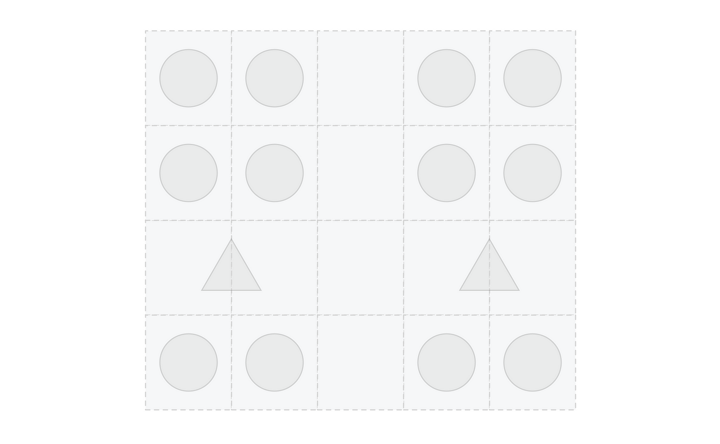
We would use graphics for the seats and use empty cells for the aisles. Also for the amenities, toilets, and kitchen, we would use custom cut assets that could pan over multiple cells inside the grid. This would allow us to have a simple system that would cover the majority of the layouts.
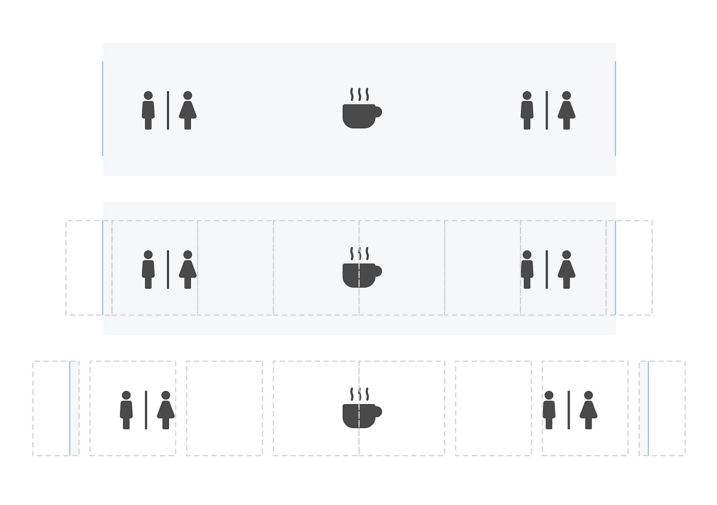
While it may seem straightforward, implementing a grid layout to render a seat map does come with some very unique challenges. The main challenge was the logic for drawing the abstract airplane that's made of different cabins, seats, and amenities.
Making Adjustments
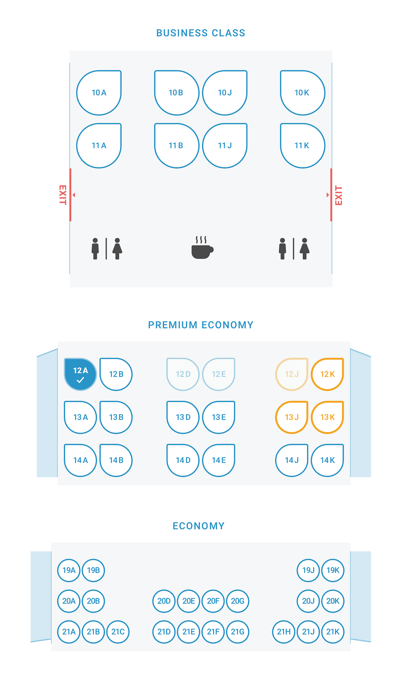
Our initial draft provided a good solution for rendering amenities and a solid general outline for drawing the seat map. However, when we looked at a multi-cabin aircraft we noticed the seats in the First class, Business class and Economy don't necessarily align with one another. Nor are they proportionally sized/positioned inside the aircraft.
If we were to force-fit the position to fit in a general grid layout, we would get a lot of jarring empty spaces or completely disproportionate seat sizes depending on the cabins. There had to be another way.
We realized while one grid layout for the entire plane would not work, we could however create separate grid layouts for each cabin. We could draw the layout of each cabin based on cabin types and the number of seats in each row.
The second issue we faced was while this grid layout worked perfectly for each cabin, how could we show the entire plane and put the cabins together. Since we were drawing each cabin separately and based on their types and number of seats, the calculated width of the plane was different.
Math to the rescue
We tried out different ideas, but none seemed to be optimal to cover the majority of the layouts. What we needed was some sort of algorithm that could define the optimal width that'd work for all cabins.
It was clearly a mathematical problem. It was also difficult to communicate the math before attempting to solve it. The best way to solve this type of problem is to write down all the variables and see if you can make a meaningful equation out of them.
The main parameters were basically the width of the grid (which was the width of the airplane) and the size of each cell (for seats, aisles and amenities). Once we put down these variables, it was easy to create a basic equation:
                      Cabin 1
WidthOfAircraft = (NumOfSeatInCabin1*WidthOfSeatInCab1) + (NumOfAisleInCabin1*WidthOfAisleInCabin1)                      Cabin 2
WidthOfAircraft = (NumOfSeatInCabin1*WidthOfSeatInCab2) + (NumOfAisleInCabin1*WidthOfAisleInCabin2)                      Cabin 3
WidthOfAircraft = (NumOfSeatInCabin3*WidthOfSeatInCab3) + (NumOfAisleInCabin3*WidthOfAisleInCabin3)
This was by far the most mind-boggling part of designing the rendering system.
Once we were able to visualize and clearly communicate the problem, it became much easier to solve the problem. After all, a "problem well stated is a problem half solved."
There are many answers that would satisfy our equation, but to get the optimal answer we needed to add some conditions to the equation.
We had to have fixed sizes for the seats, so the seat shapes wouldn't get too small or too big and we needed to let the size of the aisle cells adjust accordingly. We also wanted to keep the aisle cells visually proportional to its cabin as well as the whole plane.
Therefore we set a min-width for each aisle cell for each cabin.
Now by adding the fixed parameters as well as the min-width restrictions, we had a very solvable equation.
My initial idea to solve this equation was to start with a number for the width and then keep incrementing it by one until the equation was satisfied. Note that the ideal width we needed was the smallest number we could find for the width that would work for all cabins. This method worked but it was not ideal. I knew somebody with a strong math background could come up with a better solution.
So I called up my buddy who has a PhD in Mathematics and asked him if he could solve this equation for me. Sure enough, he came back with an elegant formula that could be easily translated into code and we were all set.
Here's how he solved it:
For any particular class (say, Premium) you have decided to require the following condition:
aisleWidth >= minAisleWidth You can then multiply both sides of that inequality by `numAisles` and then add "numSeats * seatWidth" on both sides, and obtain the equivalent inequality:
numSeats * seatWidth + numAisles * aisleWidth >= numSeats * seatWidth + numAisles * minAisleWidth` Now, the left-hand side of that equation is simply planeWidth, so you have:
planeWidth >= numSeats * seatWidth + numAisles * minAisleWidth This is true for every single class. The left-hand side is always the same, but the right-hand side depends on your class. We can call the right hand side w(Class). So you have the inequalities:
          planeWidth >= w(Econ)
planeWidth >= w(Premium)
planeWidth >= w(Business)
These three inequalities are equivalent to the single inequality:
planeWidth >= max(w(Econ), w(Premium), w(Business)) But you want planeWidth to be "as small as possible" so the optimal solution is the equality.
planeWidth == max(w(Econ), w(Premium), w(Business)) And that was it! (:
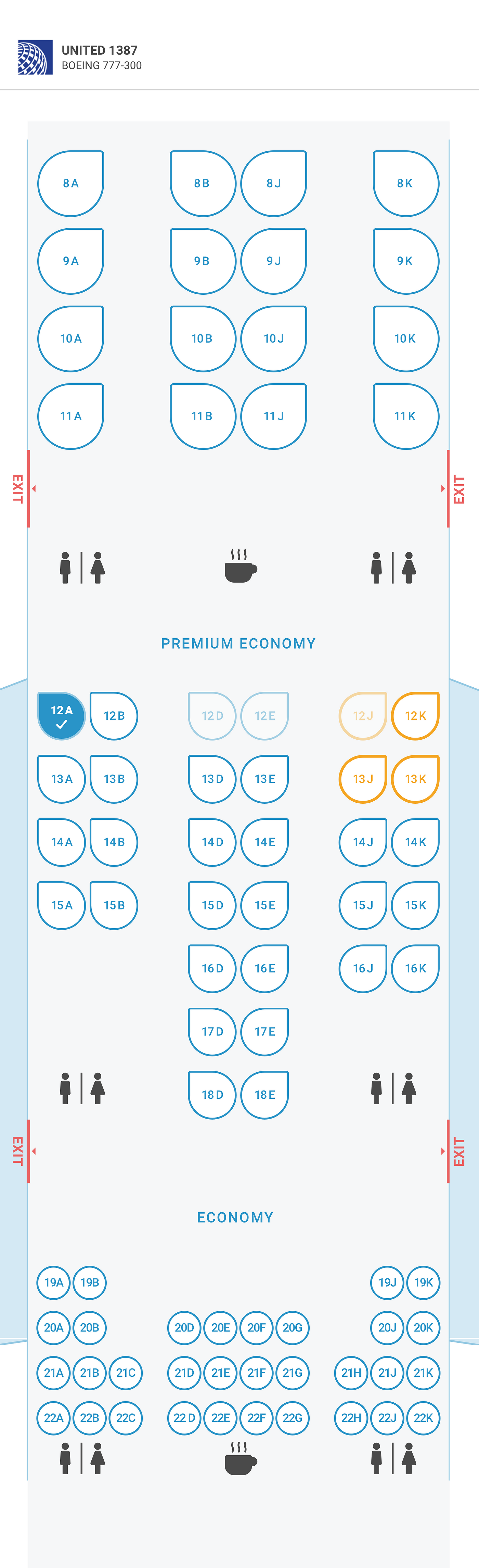
Final SeatMap Design
How Is Math Used in Industrial Design
Source: https://uxdesign.cc/when-design-engineering-mathematics-come-together-daf45a911258
0 Response to "How Is Math Used in Industrial Design"
Mag-post ng isang Komento